STM32 Bare-Metal LED: Minimal Code to Turn It On Without HAL
If you're interested in how to turn on an LED on STM32 without HAL, this guide is for you. We’ll walk through the bare-metal approach to turning on an LED with minimal code. Perfect for understanding how STM32 hardware really works under the hood. No HAL – just simple, direct register manipulation to get that LED glowing.
As you may know, we can control our MCU by directly modifying its registers. To find the correct register to turn on the LED, we need to download the MCU's reference manual and the schematic for our board (you can find in on the ST microelectronics site).
In this guide, we will use one of the onboard LEDs. Let’s take a look at the schematic and find the block with our LEDs.
Okay, I'm going to use LED4, which is connected to the PD12 GPIO pin.
To turn it on, we need to enable and configure three different peripheral blocks in our MCU:
Configure the MCU’s clock system.
Set up the GPIO mode register (so the MCU knows whether this pin will be used as input, output, analog, etc.).
Configure the output data register to control the GPIO and, in turn, the LED.
The block diagram will help us understand exactly which registers we need to configure for these peripherals. The GPIO ports are connected to the AHB1 bus, so keep that in mind.
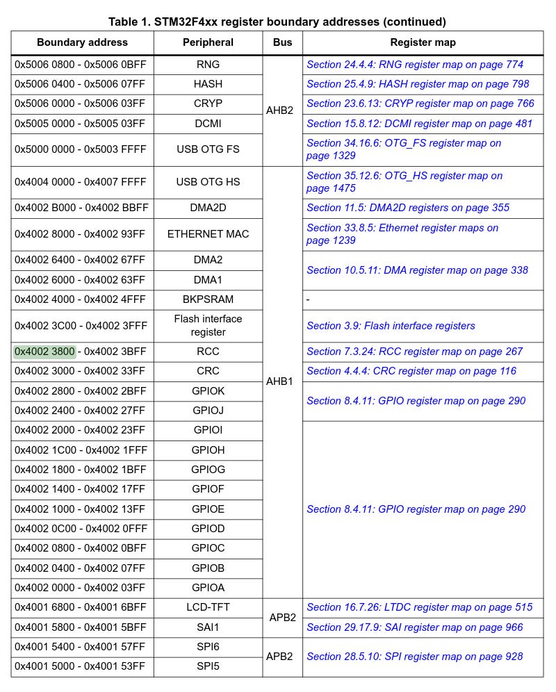
It’s time to open the reference manual and find the memory map — this will be our starting point. Let’s locate the base address of the RCC registers.
For my MCU, it is 0x40023800.
After that, we’ll move to the RCC register section to find the full RCC register map — this will be our first step. We need to configure the AHB1 bus clock to enable our GPIO.
We need to access RCC_AHB1ENR and set the GPIODEN bit high.
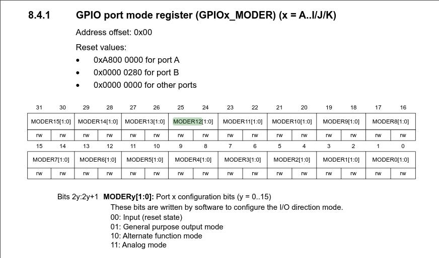
After that, we’ll move on to another register called GPIOx_MODER. You can find it in the memory map, and we will also need to get the base address of the GPIO.
This register has two bits for each GPIO pin, so we need to set bit 24 to HIGH and bit 25 to LOW. This tells the MCU that the pin will be used as an output (01: General purpose output mode).
The last step is to work with GPIO_ODR. We need to tell the MCU that we want to set pin 12 to HIGH in order to turn on the LED.
Here, we need to set bit 12 to HIGH.
Now, let’s put it all into code.
You can find the full version on GitHub.
That’s it! As you can see, the complexity hidden behind HAL really comes down to just modifying a few bits in our MCU.
Thanks for reading, and stay tuned!


