

Getting Started with STM32 GPIO: Basics of Input and Output
Quick Reference: GPIO Configuration on STM32

GPIO input mode
Let’s start with input mode. Almost all the information you need to know is on this page.

The I/O pin itself.
The pull-up resistor.
The pull-down resistor.
The input data register (IDR - the place where the value from the pin is stored).
The sequence to enable the GPIO peripheral is the same as in the previous article, except that after enabling the RCC_AHB1ENR register, you don’t need to configure the MODER register, because input mode is set to 00 by default. So, after configuring the clock for the AHB1 bus, the pin is ready to receive data. And you can start to read data from IDR.
But the MCU has no configured setup for the GPIO registers, which means the pins are floating. If nothing is connected to the pin, it may pick up noise, resulting in undefined logic levels.
Let’s take a look at an example of how to connect a button to the GPIO pin.

Hence, we have two cases:
The button is released
The pin is not connected to GND
Pull-up resistor keeps it HIGH →
GPIOx->IDRbit = 1
The button is pressed
The pin is connected to GND through the button
Logic level becomes LOW →
GPIOx->IDRbit = 0
Therefore, it's important to configure the GPIOx_PUPDR register to ensure reliable readings in case the pin might be left floating (high-impedance state).
Summarizing the results, we get the following steps to configure GPIO input mode:
Configure the
RCCregister to enable theAHB1bus.Configure the
GPIOx_PUPDRregister in case the pin might be left floating.Read data from the
IDRregister.
GPIO output mode

Push/Pull mode
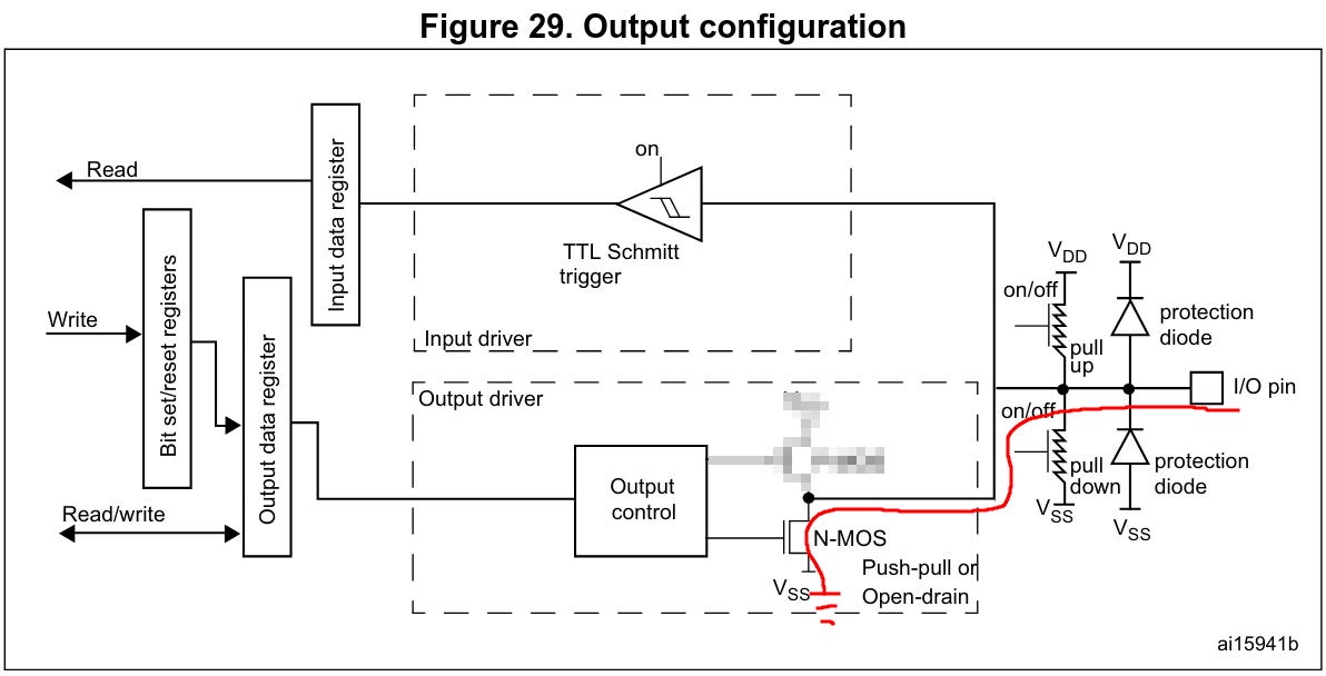
The output configuration for push-pull mode is easy.
Since the mode is controlled by two internal transistors(1 on the picture above), we always have the correct signal on the pin without a floating state.
Let's quickly go through the registers we need to configure:
RCC_AHB1ENR: enables the clock for our GPIO peripheral.MODER: we configure the GPIO pin to output mode.(Optional)
OSPEEDR: it's good to keep in mind to configure the speed of the output pin if necessary.Read data from the
ODRregister.
Open drain mode
In open-drain mode, the MCU can pull the pin low (connect to GND), but cannot drive it high.
Instead, you must use an external pull-up resistor (or internal one, if available) to bring the line high when the pin is not actively pulling low.
This setup allows multiple devices to share the same line safely – only one device pulls low at a time, and no one tries to force it high.
This is ideal for:
I²C communication
Interrupt lines from multiple sources
Bus sharing or wired-AND logic
Let's quickly go through the registers we need to configure output in open-drain mode:
RCC_AHB1ENR: enables the clock for our GPIO peripheral.MODER: we configure the GPIO pin to output mode.GPIOx_OTYPER:set the corresponding bit inGPIOx_OTYPERto 1 to configure the pin in open-drain mode.Output Types:
0: Push-pull (default)
1: Open-drain
GPIOx_PUPDR:Set the appropriate bits in theGPIOx_PUPDRregister to enable pull-up mode for a GPIO pin.00– No pull-up/pull-down (floating)01– Pull-up10– Pull-down11– Reserved
Read data from the
ODRregister.
P.S.
Be careful with pin numbers and double-check them, because some pins may be reserved for specific tasks.
For example, PA13 is used as SWDIO (Serial Wire Debug).
You may encounter problems if you try to use this pin for another purpose.